Reverse Engineering Services: How We Recreate Parts Without Original Drawings
If you have a worn-out part, a discontinued component, or a piece of equipment with no drawings on file, reverse engineering may be the most straightforward path to getting it back in production. We measure your existing part, build a CAD model from it, and machine the replacement to match — no original documentation required.
What is reverse engineering?
Reverse engineering is the process of taking a physical part and recreating its geometry in a digital format. Once we have an accurate CAD model, we can machine new parts from it — in the same material as the original, or in an upgraded material if needed.
The basic steps are:
- Inspect the sample part — We examine the part for wear, damage, and critical features.
- Measure and capture geometry — Using calipers, CMM, or 3D scanning depending on part complexity.
- Build the CAD model — A clean, machinable model is created from the measurement data.
- Machine and verify — Parts are machined and checked against the original sample.
When do you need it?
Legacy machinery parts
Older equipment often outlives the manufacturer. If your supplier no longer exists or no longer makes the part, reverse engineering from a working sample is usually the most reliable option.
Discontinued OEM components
Manufacturers discontinue parts regularly. Rather than replacing an entire assembly, we can reproduce the specific component you need.
Broken or worn parts with no drawings
Many in-house tooling pieces and fixtures were made years ago with no documentation. We can recreate them from a worn sample, often improving the geometry in the process.
Competitive analysis and improvement
Some customers bring us a competitor’s part they want to understand or improve upon. We can reproduce it accurately, or work with you to modify the design for better performance.
Measurement Tools We Use
Choosing the right measurement tool depends on the geometry of the part, the tolerances required, and how much surface detail needs to be captured. In practice, most parts require more than one tool. We use the following equipment across our reverse engineering workflow.
3D Scanner
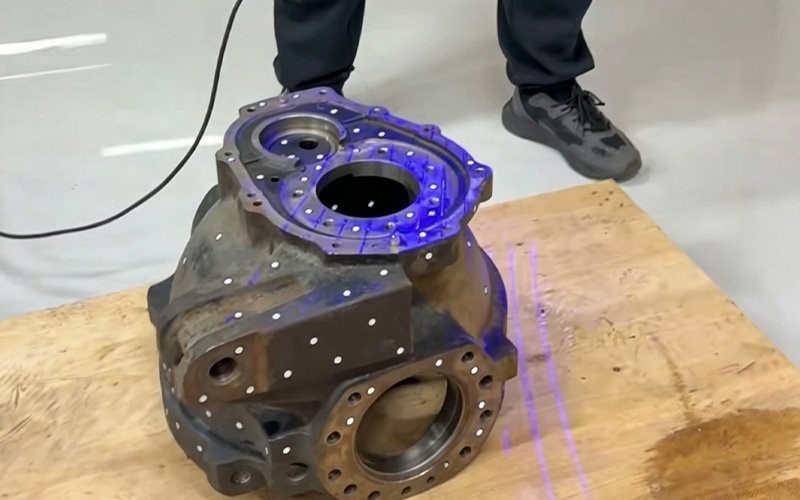
Our 3D scanner capturing the full geometry of a gearbox housing. White reference markers ensure accurate alignment across multiple scan passes.
A 3D scanner captures the full surface geometry of a part quickly and outputs a dense point cloud or mesh. We use it for parts with complex curved surfaces, organic shapes, or fine surface details that are difficult to measure by hand. The resulting data is imported directly into CAD software for model reconstruction.
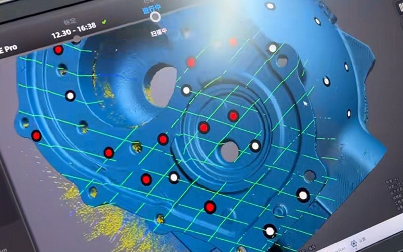
The scan data viewed in software after capture. Red and white markers indicate reference points used to align multiple scans before CAD model reconstruction.
For parts up to 500 mm (19.7″) in size, our scanner achieves a maximum accuracy of ±0.003 mm (0.00012″).
2D Profile Projector
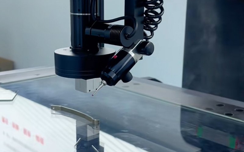
The contact probe of our 2D profile projector precisely tracing the surface of a flat metal part. This method is ideal for thin profiles, contours, and features difficult to access with handheld tools.
A profile projector casts a magnified shadow of the part onto a screen, allowing us to measure its 2D profile accurately. It is particularly useful for small parts, thin cross-sections, cutting tool profiles, and features that are difficult to access with contact probes. Fast and reliable for checking contours and angles.
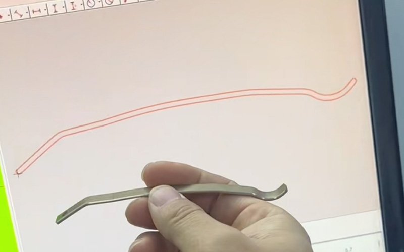
The measured 2D profile of a curved metal part displayed in software. The red outline captures the exact contour geometry, which is then used to verify dimensions or reconstruct the CAD profile.
Accuracy: ±0.003 mm (±0.00012″).
Coordinate Measuring Machine (CMM)
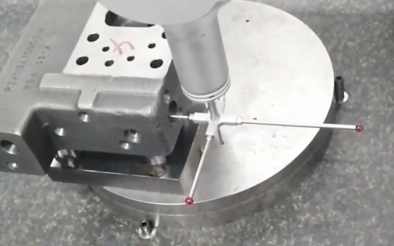
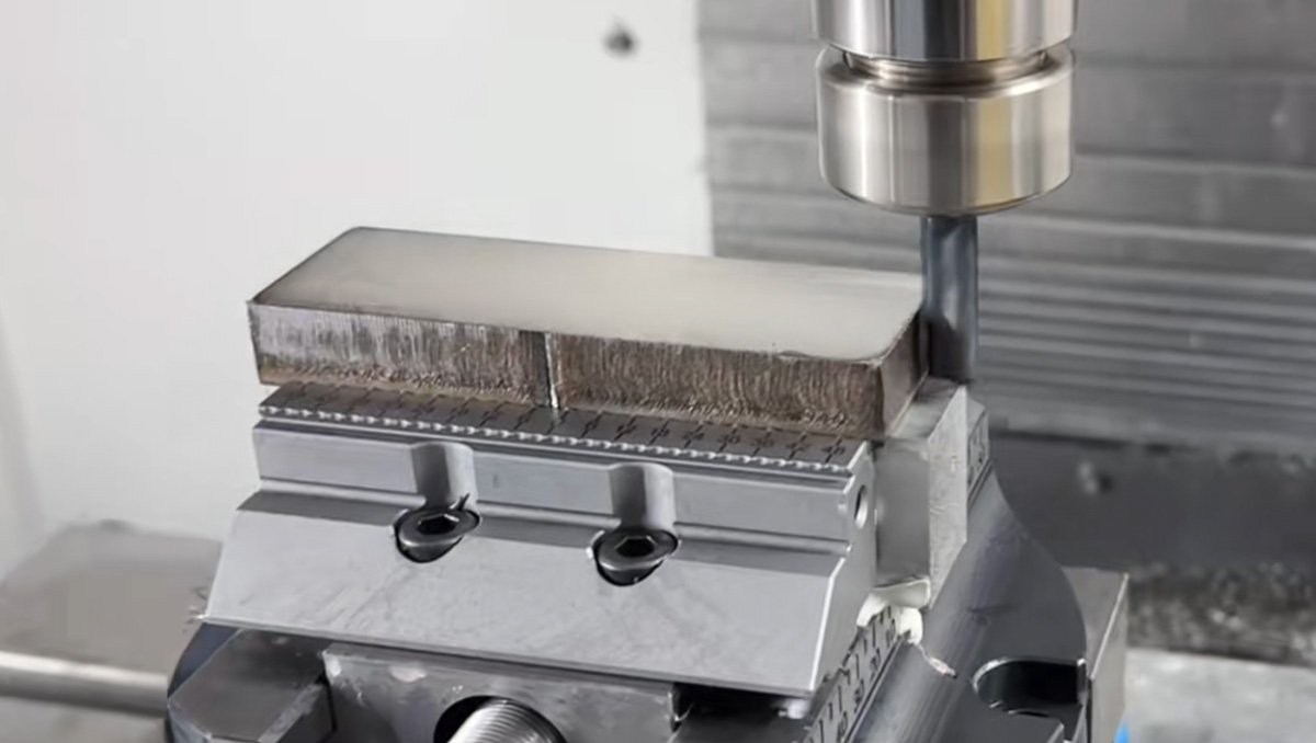
Our CMM equipped with a star probe capturing multiple measurement points across a complex machined part in a single setup. This configuration allows us to measure holes, bores, and internal features without repositioning the part.
A CMM uses a precision contact probe to measure specific points on a part in three dimensions. It is our primary tool for parts that require tight tolerances and precise geometric verification — holes, bores, flatness, concentricity, and similar features. CMM data feeds directly into our CAD reconstruction and quality control reports.
Accuracy: ±0.002 mm (±0.000079″).
Height Gauge
A height gauge measures vertical dimensions and step heights relative to a reference surface. We use it alongside a surface plate to check shoulder heights, step features, and datum surfaces quickly during both measurement and inspection stages.
Micrometer
A micrometer is used for precise linear measurements of diameters, thicknesses, and widths. It is one of the most common tools in our measurement workflow — reliable, fast, and accurate enough for the majority of standard machined features. We use outside micrometers, inside micrometers, and depth micrometers depending on the feature being measured.
Materials
We work with most common engineering materials. If you are unsure what material your original part is made from, we can help identify it.
FAQ: Reverse Engineering & CNC Machining
Not sure if your part is a good fit?
You don’t need drawings, specs, or a purchase order to start. Just send us a photo and tell us what the part does. We’ll take it from there.No commitment. No minimum order. Just answers. Start Your Project Today→!
Share this article

Written by : Alex
A quick overview of the topics covered in this article.